Description
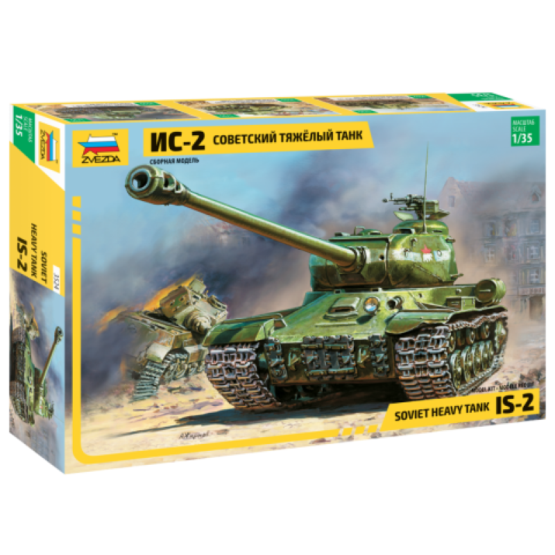
This kit represents an IS-2 from the early months of 1945 with a hull from Factory No.200. The kit includes the 12.7mm DShK machine gun mounted on the commander’s cupola, a common feature from the end of 1944 onward.
Steps 1 and 2 of the kit instructions deal with the lower hull. Unlike most Asian manufacturers who provide a one-piece lower hull tub, Zvezda molds the lower hull in separate components; the bottom including the lower front and lower rear hull are molded in one piece, to which separate sides must be attached. This simplifies the molding but often leads to the lower hull warping, which was the case with my example. This can be corrected with patience and careful gluing however.
The suspension swing arms are separate parts, as are the shock absorbers. The swing arms are keyed to square holes on the mounts, which are integrally molded with the hull sides, to ensure correct alignment. The swing arms lack detail on the ends of the torsion bars, and all the arms in my example featured sink holes that will require filling. The idler adjustment mechanism is molded integrally with the hull side, though the idler mount is a separate component and is adjustable.
Steps 3 and 4 cover the running gear. The road wheels and idlers are molded in two halves and are close to correct in diameter. However, the contours of the hubs are too square and lack the grease nipple in the center of the hub. The return rollers are the later pattern with three large lightening holes, appropriate for a vehicle built from June 1944 onward. The sprockets are molded in two halves with separate hubs.
Step 5 covers the mud scrapers for the drive sprockets. These must be attached after the sprockets, but I recommend leaving the entire running gear off the model until after painting.
Step 6 deals with the tracks though again, I recommend leaving them off the model until after painting. The kit provides ‘rubber-band’ tracks, each of which is molded in two sections. The tracks will not accept styrene cement and must be attached by melting over the pins on the ends of each section with a hot blade. The tracks represent the split-link type common on early IS series vehicles, but which persisted in service until the end of the war. The tracks lack the prominent hollows on the outer faces of the links with guide teeth.
Steps 7, 8 and 9 cover the turret assembly. The mount for the 12.7mm DShK machine gun is molded integrally with the hatch ring (part C9). It is rather thick and will benefit from thinning down with a sharp hobby knife or file.
The gun barrel is molded in two halves, along with the TsAKB muzzle brake. The muzzle brake lacks the small brackets and attachment grub screws. The mantlet (part C18) represents the wider pattern introduced at the same time as the Tsh-17 sight. It lacks the diagonal cut-out on the upper corner above the sighting aperture, but while this was present on most vehicles, it was not a universal feature.
The rain guard above the upper edge of the mantlet (part C4) lacks the hinged front section. This must be added by scribing the join line into the part and adding the hinges from thin rod or wire.
The turret features Mk.IV vision devices for the gunner and loader, which are appropriate for a vehicle manufactured after the late spring of 1944.
Step 10 deals with the DShK machine gun. The weapon and its mount are comprised of five pieces, though detail is a little crude compared to the equivalent Tamiya parts.
Step 10 also covers the assembly of the fender stowage box and the external fuel tanks. The tanks are molded with the central section in two halves split horizontally, with one piece ends that incorporate the mounting brackets and hardware as well as the lifting handles on each end. The retaining straps are rather thick and should be sanded down for a better appearance.
Step 11 covers final assembly of the turret. The fairing for the rear-facing machine gun mount (part C16) was part of the main turret shell on the real vehicle and should be faired into the main turret shell with putty. The DT machine gun itself is molded integrally with the armored shield on the mount.
The kit provides hand rails for both the upper and lower edges of the turret rear and sides. The lower rails were not fitted to all vehicles, so check your references for the specific vehicle you are modeling.
Step 12 deals with the upper hull. The upper hull molding itself (part C1) has the engine air intake screens and radiator exhaust grille molded integrally. The mesh on the intake screens is quite finely represented but the frames are too thin and lack bolt detail. I recommend replacing them with aftermarket items. The exhaust grille lacks the undercuts beneath the angled louvres but this is scarcely noticeable on the finished model.
The lifting eyes and rings are molded integrally with the upper hull and are very finely rendered. Even though they are not separate moldings, they will respond well to careful painting and provide an acceptable appearance.
The instructions have you mount the headlamp and siren to the left of the driver’s visor, which is correct for a 1945 production example. If you wish to model an earlier vehicle from 1944, mount the headlamp and siren on the opposite side. You can still use the DShK machine gun since this was retro-fitted to many earlier vehicles in the first months of 1944. Note that the instructions show the siren mounted with its aperture facing to the rear. Most photographs show the siren facing to the front.
Step 13 mounts the upper rear hull plate (part C21) to the upper hull. As noted above, the lifting eyes and rings are molded integrally with the upper rear hull plate. The kit lacks the central lifting eye between the small inspection hatches but photographs show this eye to be absent on many vehicles by 1945.
The upper rear hull plate also includes the rain gutter above the larger maintenance hatch, but the rounded shape more closely resembles the rubber sealing strip fitted to post-war vehicles. To more correctly represent a wartime vehicle, remove the molded on fitting and replace it with styrene strip.
The kit lacks the retaining brackets for the tow cables on the upper corners of the upper rear hull plate. It also lacks the spring loaded retaining clips for the front and rear towing shackles. No tow cables are provided.
The instructions direct you to mount the spare track links on the lower rear hull plate in a diagonal configuration. I have not found any photographic evidence to support this configuration, and recommend that you mount the two links horizontally instead.
The kit provides two marking options:
Soviet Army, Battle of Berlin, 1945. Though not stated in the kit instructions, this is a vehicle from the 7th Independent Guards Heavy Tank Brigade.
Soviet Army, winter 1945. This is possibly a vehicle from the 78th Independent Guards Heavy Tank Regiment.
Both of these vehicles are finished in overall Protective Green 4BO.

